
News and Trends
Seals/Oil Seals Basic Knowledge (Graphic and Text)
2018/10/15
Viewed:
Sealed knowledge
Detailed Explanation of Oil Seals (Part 1)
1. What is an oil seal?
An oil seal is a sealing element used to seal the oil around the rotating shaft in mechanical equipment. The cavity is basically stationary (see the figure below), so the oil seal is also known as a rotary shaft lip seal. Application parts of the oil seal
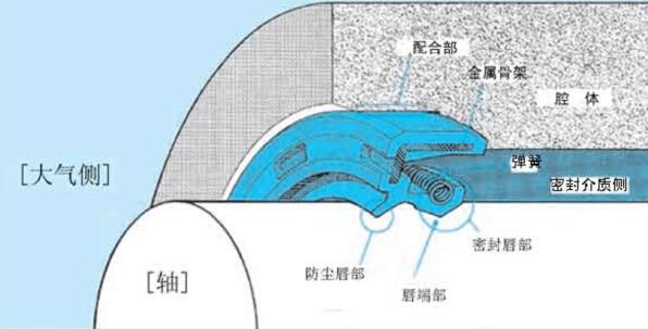
The friction parts of the machinery have oil entering during operation. To prevent this oil from leaking through the gaps of the machinery, oil seals are used. In addition to oil, it is also necessary to prevent the leakage of water and chemical liquids, as well as the intrusion of dust, dirt, and sand from the outside. In such cases, oil seals are also required.
The sealing state of the oil seal is as follows. Firstly, the outer edge of the oil seal and the cavity are in a static seal, and at the same time, it ensures the reliable positioning of the outer edge of the oil seal in the cavity. Secondly, it is the sealing state between the sealing lip of the oil seal and the shaft. When the shaft rotates, it is a dynamic seal, and when the shaft is stationary, it is a static seal. The combined effect of various influencing factors and their interactions have a significant impact on the sealing performance and service life of the oil seal.
2. Main uses of oil seals
Used for the sealing of engine crankshafts and camshafts
Sealing of transmission systems (such as gearboxes, wheel hubs, axle shafts, differentials) for cars, motorcycles, and commercial vehicles
Sealing of the transmission systems of agricultural and construction machinery such as forklifts and excavators
Sealing of industrial gearboxes
Sealing of hydraulic components (pumps, motors)
Sealing of daily-use mechanical washing machines
Widely used in mechanical engineering and equipment processing industries
3. Main characteristics of oil seals
The outer part of the oil seal is cylindrical to ensure static sealing of the cavity. The rubber outer edge with an internal metal skeleton is used; for the outer edge with an exposed metal skeleton, polishing and application of an anti-corrosion coating are mostly required.
The spring-loaded sealing lip ensures the sealing reliability of the shaft for both dynamic and static seals. As a result of long-term development and research, the structure of the oil seal's sealing lip has been improved to achieve optimal performance, thereby enhancing the sealing reliability within a wide load range.
Adding a dust-proof lip, or in special cases, multiple dust-proof lips, can prevent the intrusion of external contaminants and dust.
Detailed Explanation of Oil Seal (II)
4. Functions of each part of the oil seal
The oil seal is mainly composed of several parts such as the sealing body, reinforcing skeleton, and self-tightening spiral spring. The sealing body is divided into the bottom, waist, cutting edge, sealing lip, etc. according to different parts. The following figure shows: the main names and terms of each part of the inner skeleton oil seal with a spring and a dust-proof lip. The application part of the oil seal
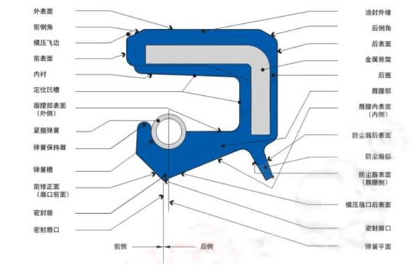
The metal skeleton is like the steel bars in concrete components, playing a strengthening role and enabling the oil seal to maintain its shape and tension. Usually, for a skeleton oil seal in a free state, its inner diameter is smaller than the shaft diameter, that is, it has an "interference fit". Therefore, after the oil seal is installed in the oil seal seat and on the shaft, the pressure of the oil seal lip and the contraction force of the self - tightening spiral spring generate a radial tightening force on the shaft. After a period of operation, this pressure will rapidly decrease and even disappear. Thus, adding a spring can compensate for the self - tightening force of the oil seal at any time.
The outer edge of the oil seal not only fixes the oil seal in the cavity hole, but also prevents the leakage and intrusion of fluid between the outer peripheral surface of the oil seal and the inner surface of the cavity. In addition, when the oil seal is fixed in the cavity, the metal skeleton plays a role in maintaining the matching force.
The sealing lip is made of flexible elastomer, designed to maintain a stable sealing effect even under the influence of mechanical vibrations and pressure fluctuations of the sealed fluid, and to keep the lip in a stable contact state with the shaft surface. The spring can increase the pressing force of the sealing lip towards the shaft and maintain this pressing force. The end of the lip is made into a wedge shape, pressing against the shaft surface at the end to seal the fluid.
The dust-proof lip is a secondary lip that is not connected to the spring and serves to prevent dust from intruding.
5. Main types of oil seals
For various types of oil seals, please refer to: Common Oil Seal Structural Types; Common NOK Standard Oil Seal Types. Attached figure: Various design types of the outer edge of the oil seal.

6. Sealing Mechanism of Oil Seal
The sealing mechanism of the oil seal involves two factors. One is the sealing of the cavity, mainly the positioning of the outer edge of the oil seal (static component) in the cavity. The second is the dynamic sealing where the sealing lip contacts the surface of the rotating shaft, which is an important function of the oil seal. Attached below is a diagram: The contact area between the sealing lip of the oil seal and the surface of the rotating shaft.
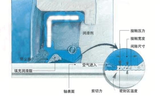
In order to ensure the static seal of the oil seal in the cavity and its stable positioning in the hole, and to facilitate assembly, the outer edge of the oil seal is generally made of a metal skeleton coated with rubber material, combining the reliable static sealing ability of the rubber elastomer with the advantages of the metal skeleton for support and positioning. The outer edge of the oil seal is designed with a chamfer for easy assembly. Additionally, some oil seals are designed with grooves on the outer edge to increase adhesion, avoid the risk of the oil seal retreating and tilting, and also increase the press fit tolerance, which can improve the reliability of the static seal of the oil seal. Oil seals with a metal outer skeleton design for the outer edge are suitable for applications where a firm installation in the cavity is required. It should be noted that when the inner surface of the oil seal seat hole is rough, a sealant should be applied, and a sealant can be used at the seal seat.
The sealing mechanism in the contact area of the oil seal's sealing lip is of great significance to the sealing function of the oil seal. It depends on: the design of the sealing lip; the structure of the elastic material; the roughness of the shaft surface, etc. The combined effect of the radial force of the sealing lip, the angle design of the sealing lip, and the distance design between the lip tip and the spring center generates a contact pressure that is asymmetrically distributed on the shaft surface: the pressure is high and rises steeply on the oil side; the pressure decays at a small angle on the air side. With the interference fit (the inner diameter of the sealing lip is designed to be slightly smaller than the diameter of the shaft in the free, unloaded state), this asymmetric distribution of contact pressure, combined with the circumferential hoop force generated by the rotating shaft, leads to the deformation of the structural characteristics in the contact area of the sealing lip. This deformed structure of the sealing elastomer is formed during the trial operation of the oil seal and plays a decisive role in the sealing performance (therefore, the oil seal requires a running-in period during the trial operation). The influence of the spiral line, combined with the rotation of the shaft, generates a pumping action towards the oil side from this deformed structure.
Detailed Explanation of Oil Seal (IV)
7. Raw materials for oil seals
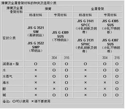
The skeleton and spring of the oil seal are made of metal, and the main parts such as the sealing lip are made of rubber. According to the usage environment, different rubbers can be used to produce oil seals to meet the sealing performance and requirements. The commonly used oil-resistant rubber is nitrile-butadiene rubber, which is one of the most commonly used rubbers for oil seals and O-rings at present. It can be said that it is a rubber seal with a wide range of uses and low cost at present. Other rubbers commonly used in manufacturing oil seals include polyacrylate rubber, silicone rubber, fluororubber, and polytetrafluoroethylene. For the performance of various rubbers, please refer to: Types and Characteristics of Main Rubbers. Attached below is a figure: Types of Spring and Metal Skeleton Materials and Applicable Media
8. Sealing media of oil seals
The occasions where oil seals are used typically involve sealing media such as mineral lubricating oils, greases, synthetic lubricating oils, and greases. Additionally, they can seal DIN51524 hydraulic oils, VDMA24317 and VDMA24320 highly flame - retardant hydraulic oils, and silicone oils with low lubrication characteristics used in industrial production. In special cases, they can also seal corrosive media with low lubricity, such as acids, alkalis, and organic solvents.
Generally, the oil seals made of fluororubber material have better corrosion resistance and high - temperature resistance than those made of NBR material. Under the conditions of no lubrication, pure dryness and multiple media, it is recommended to use oil seals with PTFE sealing lips. The sealing lips have sufficient lubrication ability, which greatly reduces the wear of the lip edge. A single oil seal is not suitable for sealing two different media. A large number of chemical substances increase the impact on the performance of the oil seal material. The compatibility of the oil seal with the sealed medium should be determined through laboratory tests. Attached is the following figure: Adaptability of different rubbers for oil seals to the sealed medium
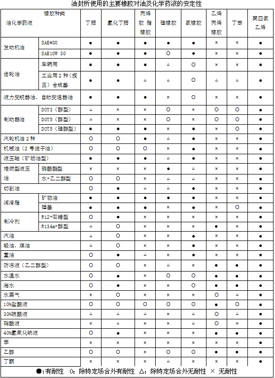
The contamination of the sealing medium may be the sand residue left over from the manufacturing process of the cavity casting; or the particulate matter generated from the friction and wear of the rotating components. For example, the wear debris of the bronze turbine in the turbine gearbox; or the products generated by the corrosive medium. To prevent the adverse effects of the contamination of the sealing medium on the sealing characteristics, attention should be paid to keeping the cavity as clean as possible.
9. Main requirements for oil seals
1. Good sealing performance
2. High reliability
3. Easy to assemble
4. Compatible with the sealed medium
5. Low friction
Detailed Explanation of Oil Seal (V)
10. Influencing Factors in the Selection of Oil Seals
In order to give full play to the functions of the oil seal, select the appropriate type and material according to the operating conditions. Here is a brief description of the main influencing factors.
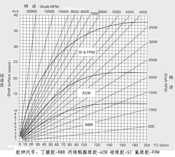
1. Surface linear velocity of the shaft: Under the condition of the same diameter, oil seals made of different materials have different abilities to adapt to the linear velocity of the shaft surface rotation, and the relationship is shown in the figure below. The linear velocity range of the oil seal is generally less than 15m/s. The allowable surface linear velocity of the shaft given in the figure below is a reference value. Satisfactory lubrication and good heat dissipation conditions are the decisive factors. The relatively lower data is applicable to more severe conditions.
2. Temperature: Due to the friction between the surface of the rotating shaft and the sealing lip of the oil seal, the temperature at the sealing lip is higher than that in the oil. Generally, when the oil seal is working, the temperature of its lip edge is 20 - 50℃ higher than that of the working medium. As the rotational speed increases and the pressure rises, the temperature at the sealing lip also increases. In addition, the oil seal with a dust - proof lip will have a temperature 20℃ higher than that without a dust - proof lip. When the temperature exceeds the allowable temperature, the working life of the oil seal will be shortened, resulting in premature hardening of the sealing lip and increased wear. The working temperature range of the oil seal is related to the material used: when the material is nitrile butadiene rubber (NBR), it is - 40~120℃; when it is acrylic rubber (ACM), it is - 30~180℃; when it is fluororubber (FPM), it is - 25~300℃.
3. Pressure: Oil seals are mainly used under conditions of no pressure or slight pressure, with a maximum working pressure of 0.02 - 0.05 Mpa. When the working pressure exceeds this value, pressure-resistant oil seals should be selected.
4. Dust prevention: To prevent pollutants, dust, moisture, etc. from entering the sealed cavity from the air side, it is recommended to use an oil seal with a dust lip. If the intrusion of pollutants is severe, it is recommended to use two oil seals, installed in series one after the other.
11. Design of the oil seal installation part
Design of the shaft: 1. Surface roughness: Due to the different speeds and oil quantities of the shaft, if the surface roughness of the general shaft is too large or too small, it will affect the leakage and wear of the oil seal. The allowable range of the surface roughness of the shaft is Rz1.0 - 5.0μm; Ra0.2 - 0.8μm. For oil seals on rotating shafts, take 2.5 - 1.6μm Rz. 2. Hardness: The surface hardness of the rotating shaft generally takes ≥35HRC. When the medium is dirty, there are external pollution impurities, or the surface speed of the shaft > 12m/s, the surface hardness of the shaft should be above 55HRC, and the depth of the shaft surface quenching layer > 0.mm. 3. Shaft chamfer: The recommended value is 15° - 30°; the principle is to ensure that the oil seal can be properly installed without damaging the lip of the oil seal. 4. Shaft processing: Correct shaft processing is a decisive factor in ensuring the normal operation of the sealing system. The appropriate processing method for the oil seal shaft is fine grinding with transverse feed and polishing with emery paper. The inappropriate processing methods are finish machining on a lathe, superfinishing, burnishing, and polishing with emery paper (the sandpaper is polished in the axial direction). 5. Shaft material: It is mainly ordinary carbon structural steel, such as C35 and C45. In addition, there are also cast iron, ceramics, and resin plastics. However, the shafts made of the latter three materials have defects in the sealing of the oil seal.
Design of the cavity: 1. Surface roughness and diameter tolerance are shown in the following table.
Part diameter tolerance, surface roughness/mm Ra≤Rz≤. For seat holes, for oil seals without a framework, H11, 3.2, 12.5. For oil seals with a framework, H8 or H7, 1.6, 6.3. For rotating shafts, h9 or f9, 0.8 - 0.4, 3.2 - 1.6. 2. Recommended installation chamfer value is 15° - 30°. 3. The material of the cavity is steel or cast iron, and oil seals with an outer circumference of rubber or metal can be used. Generally, light alloys and resins have a relatively large coefficient of thermal expansion, and oil seals with a rubber outer circumference are suitable. 4. Unsuitable cavity structures, such as those processed by stamping, those installed by threaded combination, split - type cavities, etc.
Detailed Explanation of Oil Seal (VI)
12. Leakage of oil seals
When an oil seal leak is detected, first confirm the location of the leak. If it is not the oil seal that is leaking, sometimes it is mistaken for a leak due to reasons other than leakage, such as the attachment of grease. The main reasons for oil seal leakage are as follows: 1. The static sealing surface where the outer edge of the oil seal mates with the cavity is deformed due to non - compliance of dimensional tolerances with the standard specifications; 2. Material cracking is caused by overly harsh working conditions, especially cracking on the sealing edge of the oil seal; 3. The hardness of the rubber increases due to overly harsh working conditions and the incompatibility between the rubber elastomer and the working medium, or the hardness of the elastomer is high; 4. The sealing medium causes the rubber to swell, reducing the hardness of the rubber, resulting in premature aging and wear of the oil seal; 5. Corrosion from the shaft to the sealing lip area leaves potential faults in the sealing performance of the sealing system; 6. The failure of the lubricant causes the system to operate in a dry state, resulting in rapid wear of the sealing lip; 8. Comprehensive aging, where both the rubber elastomer and the sealing medium age; 9. The formation of "oil - carbon" dirt at the sealing lip causes the sealing lip edge of the oil seal to be lifted, triggering a leakage fault in the sealing system; 10. The sealing lip edge of the oil seal no longer follows the vibration of the shaft surface and the shaft run - out; 11. Contaminants embedded on the sealing edge from the inside and outside of the seal cause premature wear of the shaft surface and the sealing lip edge; 12. Irregular assembly causes damage to the contact surface of the shaft, resulting in premature wear of the sealing lip; 13. The sealing edge is damaged during storage, transportation, and assembly. Attached below is a diagram: The main reasons for leakage from the lip area:
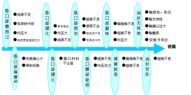
Figure 2: The main causes of leakage from the outer edge of the oil seal
When the oil seal leaks, different leakage situations should be analyzed emphatically so as to take different measures. The leakage of the oil seal at different stages should be classified as follows: 1. Watertight, with no moisture visible on the oil seal; 2. Wet, with a moisture film appearing at the sealing lip area that does not affect the sealing function, but the moisture film does not extend to the back; 3. Damp, with the moisture film extending to the back and forming water droplets, but not yet dripping continuously; 4. Measurable leakage, with a recognizable tiny liquid flow rate flowing out from the back of the oil seal visible outside the cavity; 5. Temporary leakage, a short - term failure of the sealing system, for example, caused by contaminant particles under the sealing lip, which can be washed away during continued use; 6. Obvious leakage, where temporary leakage leads to an excessive amount of grease being filled between the sealing lip and the dust - proof lip. The overflowing grease manifests as obvious leakage outside the system. In addition, the causes of leakage should be analyzed according to the time process of the oil seal's operation. For example, early breakage that leaks as soon as it is used; premature damage that starts to leak after a short period of use; damage that leaks during operation after a relatively long period of use; and leakage damage that occurs at the end of the designed service life of the oil seal, etc.
13. Transportation and Assembly of Oil Seals
1. Oil seals are precision components, and improper assembly and storage will affect their performance. When transporting and storing oil seals, the following should be noted:
1. Do not open the original packaging. Pay attention to whether the packaging is damaged. Try to keep the oil seal in the original packaging before assembly.
2. Avoid direct sunlight and do not place it near high-temperature heat sources, as this can accelerate the aging of rubber.
3. Oil seals shall not be placed randomly. Pay attention to dust and soil prevention to ensure that the oil seals are in a closed or covered state.
4. When transporting and using the oil seal, to prevent the oil seal from deforming and the spring from falling off, do not apply excessive impact.
5. The oil seal should not be tied with a thin string, nor should it be hung on a nail or metal wire, as this will damage the sealing lip.
6. Do not place the oil seal in a damp place, as this will cause the metal parts to rust.
7. Do not place the seals near televisions and areas that generate ozone.
8. Please do not rub the end of the lip with nails or hard objects to prevent damage to the sealing lip.
Secondly, for the assembly of oil seals, no matter how appropriate the design of the installation part of the oil seal and the selection of the oil seal are, if the assembly is rough, the oil seal cannot fully exert its intended function.
(1)When installing the oil seal, the outer surface should be coated with an appropriate lubricant, and the lip should be coated with a suitable clean grease. For an oil seal with a dust-proof lip, the space between the main and auxiliary lips should be filled with a suitable clean grease before assembly.
(2)Face the sealing lip end of the oil seal towards the side of the sealed medium. Do not install it in the opposite direction.
(3)When installing the oil seal into the seat hole, a special tool should be used to push it in to prevent misalignment.
(4)Measures should be taken to prevent damage to the lip of the oil seal when it passes through threads, keyways, splines, etc., and special tools should be used for assembly.
(5)The oil seal should be placed horizontally into the seat hole and pressed uniformly. Do not push it in forcibly at an angle.
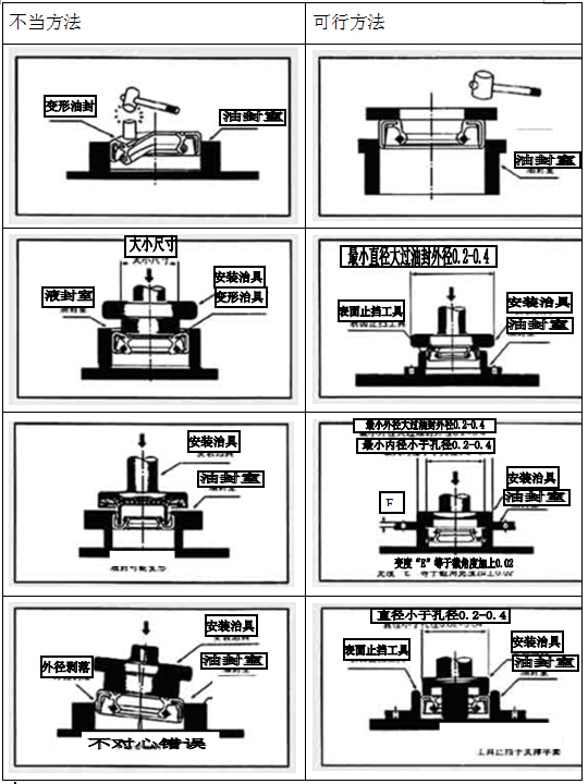
Attached below: Proper and improper methods of oil seal installation
Detailed Explanation of Oil Seals (VII)
14. Oil seal dimensions and specifications
There are various types of oil seals. Each country and manufacturer has its own marking method. Nevertheless, since oil seals are standard parts, if there is no new mold opened for special design, only the inner diameter, outer diameter, and height of the oil seal are generally given. See the figure below: Schematic diagram of oil seal size marking
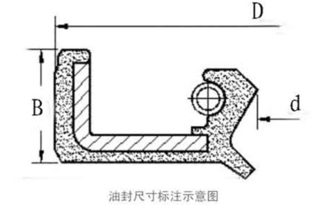
Schematic diagram of oil seal size marking
In the above figure, the small "d" represents the inner diameter of the oil seal, the large "D" represents the outer diameter of the oil seal, and "B" represents the height of the oil seal. For example, TC30*40*5 indicates a TC-type (double-lipped with metal skeleton) oil seal with an inner diameter of 30mm, an outer diameter of 40mm, and a height of 5mm. Sometimes, DIN, GB/T9877 - 88, etc. can be followed to indicate the standards on which the oil seal is based. The inner diameter size range of the oil seal is generally from Φ16 to 440mm, and the common width is from 7 to 20mm. For the specifications of the metal skeleton oil seals of our company, please refer to: the Specification Table of Self-tightening TC Oil Seals with Metal Skeleton.
15. Oil seal standards
Oil seals are important components widely used in industrial applications. To promote the rapid development of the oil seal industry, various countries have formulated and introduced a series of relevant standards. In China, the commonly applied oil seal standards are the national standard GB9877.1/2/3 - 88 series and the GB13871 - 1992 oil seal standard. HG4 - 692 - 67 is the oil seal standard proposed by the Ministry of Chemical Industry of China.
Scope of application of "GB/T9877.1 - 88": —— This standard specifies the basic structure, and the size series of the skeleton and spring of the rotary shaft lip seals with inner - cased skeleton. This standard is applicable to the rotary shaft lip seals with inner - cased skeleton installed at the end of the rotating shaft in equipment, which seal fluids and greases under the condition that the pressure difference does not exceed 0.03MPa. "GB/T 9877.2 - 1988" is the second part of the structural dimension series of rotary shaft lip seals: relevant regulations for rotary shaft lip seals with exposed skeleton.
Scope of application of "GB13871 - 1992": —— This standard specifies the basic dimensions and tolerances of rotary shaft lip seals (hereinafter referred to as "seals") with shaft diameters ranging from 6 to 400 mm and the inner hole diameters of the corresponding sealing cavities (hereinafter referred to as "cavities") ranging from 16 to 440 mm. In order to ensure the interchangeability of seals produced by different manufacturers, this standard also specifies the dimensions and tolerances of the shaft and the mounting hole. This standard is applicable to seals with a working pressure equal to or less than 0.05 MPa, and is not applicable to higher working pressures. In order to enable the seals provided by manufacturers to meet the design and use requirements, Appendix A of this standard recommends a report format related to seals for use in agreements between the supplier and the demander for both parties.
Recently, China has re - formulated the national recommended standards for oil - seal products that adapt to international development, namely "GB/T13871.1 - 2007" and "GB/T13871.4 - 2007". The new national standards were officially implemented on July 1, 2008. These standards were compiled by the Sealing Products Sub - committee of the National Technical Committee for Standardization of Rubber and Rubber Products. The new standards meet the requirements of international equivalent technical standards, raise the technical requirements for sealing products, and provide good technical guarantee for better solving the "three - leakage problem" that has long troubled Chinese enterprises. The implementation of the new standards will surely gradually promote the new development of the oil - seal products industry.
In addition, the international oil seal standards are: ISO6194 (International ISO Standard), DIN3760 (German Industrial Standard), and JIS2402 (Japanese Industrial Standard).